Hydraulic Design of Surge Shaft


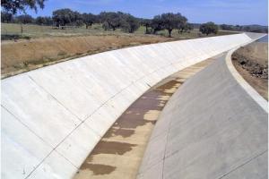
Surge shaft is a structure provided at the end of headrace tunnel or pipe to account for water hammering effect in the pipe at its downstream. Surge shaft is considered to be an important component of Hydropower projects, especially for those involving headrace pressure tunnels.
Applications of Surge Shaft
In most of the hydropower projects involving pressure tunnels when power house is suddenly shut down by closing the turbine valves the water in penstock stops suddenly and because of the inertia of incoming water from the back creates a resonance effect, which in a mean while causes water hammering effect. If no arrangement has been made to prevent this water hamming it may result in bursting of penstock pipe and may lead to serious stability issues of the hydropower project, the best solution is to provide a surge shat or surge tank depending upon the site constraints.
Design of Surge Shaft
Design of Surge Shaft depends upon different parameters such as given below:
- Design discharge
- Headrace water level
- Headrace tunnel diameter
- Headrace tunnel length
- Headrace tunnel slope
- Headrace tunnel material
Design discharge is the amount of water to be carried by the headrace tunnel of specific diameter with a pre defined longitudinal slope, greater the slope more will be the velocity of water through headrace tunnel and hence more will be head losses.
DESIGN EXAMPLE #1 (3.40m Diameter Headrace Tunnel)
DESIGN EXAMPLE #2 (2m Diameter Headrace Tunnel)
Design of surge shaft is consists of the following two parts
- Hydraulic Design
- Structural Design
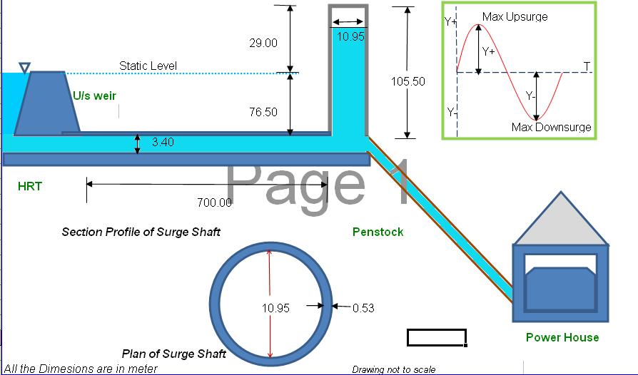
HYDRAULIC DESIGN #1
The following example will help in under standing the Design criteria and procedure for Surge Shaft.
| Basic input Data | |||
| Length of HRT |
= |
700.00 |
m |
| Diameter of HRT |
= |
3.40 |
m |
| Cross-sectional area of HRT |
= |
9.08 |
m2 |
| Net Head |
= |
40.00 |
m |
| Design Discharge |
= |
100.00 |
Cumecs |
| Headrace water level |
= |
2500.00 |
m |
| Water level at HRT entrance |
= |
2494.00 |
m |
| Factor of Safety |
= |
1.60 |
|
| Longitudnal slope of HRT |
= |
0.10 |
m/m |
| Free Board in surge shaft |
= |
0.50 |
m |
| Hydraulic Design (Instantaneous closure) | |||
| Flow velocity in HRT |
= |
11.01 |
m/s |
| Wetted Parameter |
= |
10.68 |
m |
| Mean Hydraulic Radius |
= |
0.85 |
m |
| Resistence factor of Tunnel |
= |
0.138 |
|
| Area of Surge shaft |
= |
58.81 |
m2 |
| Area of surge shaft (provd) |
= |
94.09 |
m2 |
| Diameter of surge shaft |
= |
10.95 |
m |
| Radius of surge shaft |
= |
5.475 |
m |
| Height of up surge (Dz) or |
= |
29.00 |
m |
| Height of up surge (ymax) |
= |
29.00 |
m |
|
(Above static level) |
|||
| Period of Oscillation |
= |
171 |
s |
| Water stops at T/4 |
= |
42.75 |
s |
| Velocity in HRT at Max surge |
= |
11.01 |
m/s |
| Velocity in S.T at Max surge |
= |
-1.06241 |
m/s |
| Total Height of Surge Shaft |
= |
105.50 |
m |
STRUCTURAL DESIGN #1
Structural design of surge shaft is as follows
| Basic input Data | |||
| Unit weight of water |
= |
0.000010 |
N/mm3 |
| Compressive strength of Concrete |
= |
25.00 |
N/mm2 |
| Structural Design | |||
| Surge Head Pressure |
= |
1.03 |
N/mm2 |
| Permissible compressive stress |
= |
11.15 |
N/mm2 |
| Outer Radius of surge shaft |
= |
6.01 |
m |
| Thickness of surge shaft |
= |
0.53 |
m |
| Thickness of surge shaft wall (provided) |
= |
0.53 |
m |
HYDRAULIC DESIGN #2
The following example will help in under standing the Design criteria and procedure for Surge Shaft.
| Basic input Data | |||
| Length of HRT |
= |
700.00 |
m |
| Diameter of HRT |
= |
2.00 |
m |
| Cross-sectional area of HRT |
= |
3.14 |
m2 |
| Net Head |
= |
40.00 |
m |
| Design Discharge |
= |
100.00 |
Cumecs |
| Headrace water level |
= |
2500.00 |
m |
| Water level at HRT entrance |
= |
2494.00 |
m |
| Factor of Safety |
= |
1.60 |
|
| Longitudnal slope of HRT |
= |
0.10 |
m/m |
| Free Board in surge shaft |
= |
0.50 |
m |
| Hydraulic Design (Instantaneous closure) | |||
| Flow velocity in HRT |
= |
31.83 |
m/s |
| Wetted Parameter |
= |
6.28 |
m |
| Mean Hydraulic Radius |
= |
0.50 |
m |
| Resistence factor of Tunnel |
= |
0.279 |
|
| Area of Surge shaft |
= |
10.03 |
m2 |
| Area of surge shaft (provd) |
= |
16.05 |
m2 |
| Diameter of surge shaft |
= |
4.53 |
m |
| Radius of surge shaft |
= |
2.265 |
m |
| Height of up surge (Dz) or |
= |
119.00 |
m |
| Height of up surge (ymax) |
= |
119.00 |
m |
|
(Above static level) |
|||
| Period of Oscillation |
= |
120 |
s |
| Water stops at T/4 |
= |
30 |
s |
| Velocity in HRT at Max surge |
= |
31.82 |
m/s |
| Velocity in S.T at Max surge |
= |
-6.22952 |
m/s |
| Total Height of Surge Shaft |
= |
195.50 |
m |
STRUCTURAL DESIGN #2
Structural design of surge shaft is as follows
| Basic input Data | |||
| Unit weight of water |
= |
0.000010 |
N/mm3 |
| Compressive strength of Concrete |
= |
25.00 |
N/mm2 |
| Structural Design | |||
| Surge Head Pressure |
= |
1.92 |
N/mm2 |
| Permissible compressive stress |
= |
11.15 |
N/mm2 |
| Outer Radius of surge shaft |
= |
2.69 |
m |
| Thickness of surge shaft |
= |
0.43 |
m |
| Thickness of surge shaft wall (provided) |
= |
0.43 |
m |
CONCLUSION
From the above example it can be concluded that by reducing the diameter of headrace tunnel, while keeping other factors constant velocity of water in headrace tunnel increases by 300%, thus causing high up surge waves in surge shaft with small period of oscillation. This will result increase in the height of surge shaft.