Design Optimization of Hydraulic Penstock

Design optimization is the selection of most efficient and cost effective diameter of Penstock, taking in to account its cost and benefits. Optimization is the application of mathematical tools and techniques to an engineering sector that will enable the concerned people to select the most optimum option. In hydropower projects optimization plays a vital role by increasing project efficiency at least cost.
OPTIMIZATION
Optimization is complicated process for which the project is evaluated for different available discharges , the corresponding project cost and net benefits are compared, the discharge that gives the maximum net benefits at minimum project cost is taken as the Design Discharge and the whole design calculations is made on this discharge.

Trail Diameter No 1
Trail Diameter No 2 & so on..
PENSTOCK OPTIMIZATION EXAMPLE
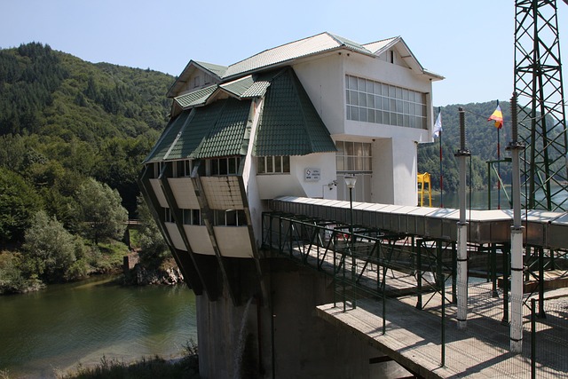
Penstock is one of the most expensive component of hydropower project and needs to be designed carefully, in this example the unit rates assumed for optimization are best applicable in Pakistan, however for other areas it can be assumed accordingly, while the rest of procedure remains the same.
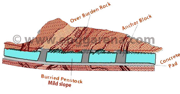
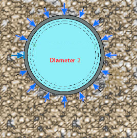
Let’s suppose a design discharge of 20 cumecs is delivered by a mild steel penstock of length 320m to the hydraulic turbines. The penstock is buried in soil with a gross head of 200m. Seven pipes of diameter 0.9m, 1.0m, 1.10m, 1.2m, 1.35m, 1.5m and 1.8m are considered for optimization, rest of design calculations is given below (assume any missing data)
BASIC INPUT DATA
|
Material of Pipe |
Mild Steel |
|
|
|
Pipe Diameter (inner) |
Di = |
1.8 |
m |
|
Head loss due to friction |
Hf = |
6.9 |
m |
|
Length of Penstock |
L = |
320 |
m |
|
Flow through Pipe |
Q = |
20 |
m3 / s |
|
Number of pipes |
N = |
1 |
no |
|
Flow per Pipe |
Q/N = |
20 |
m3 / s |
|
Gross Head |
Hg = |
200 |
m |
|
Number of Bends |
No = |
3 |
no |
|
Duration |
t = |
24 |
hr |
|
Manning's coefficient |
n = |
0.011 |
contt |
|
Corrosion allowance |
Ca = |
1.5 |
mm |
|
Efficiency (Turbine & Powerhouse) |
η = |
85 |
% |
LOSSES CALCULATIONS
|
Entry+Exit+ Gate valve Losse (0.2*V2/2g) |
2 |
1.25 |
m |
|
Bend loss Assumed (0.3*V2/2g) |
2 |
1.88 |
m |
|
Trash Rack Losses (0.25*V2/2g) |
1 |
0.78 |
m |
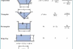
HYDRAULIC DESIGN CALCULATIONS
|
Area of cross section of the pipe |
Ap = |
2.54 |
m2 |
|
Wetted permeter |
P = |
5.65 |
m |
|
Hydraulic Radius |
R = |
0.45 |
m |
|
Hf in terms of V2 (n2 x L/ R4/3 ) |
V = |
0.11 |
m/s |
|
Velocity of the flow through the pipe |
Vp = |
7.87 |
m/s |
|
Calculated Discharge |
Q final = |
20.09 |
m3/s |
|
Losses calculations |
Hc = |
3.93 |
m |
|
Total head loss |
H loss = |
10.87 |
m |
|
Net head |
H Net = |
189.13 |
m |
|
Power |
Po = |
31.68 |
MW |
DESIGN OPTIMIZATION TABLE
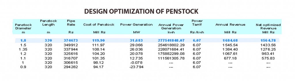
From the above calculations it is concluded that the most optimal diameter for the given data is 1.8m with Net power out of 31.68 MW and Net optimized revenue of Rs: 1564.78 Million.