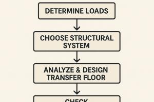
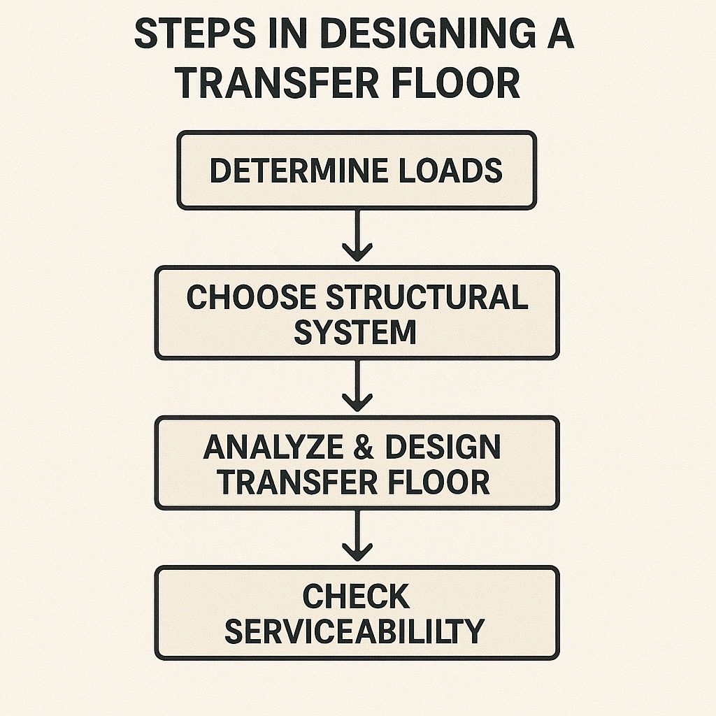
Steps in Designing a Transfer Floor

What is the Loading on a Transfer Floor?
Design of reinforced concrete transfer floors, although routinely performed by structural design engineers, is a very challenging task. The transfer floors are commonly used in multi-storey buildings, and they are major structural elements carrying a number of floors. Normally the entire building, 10 to 15 levels, is carried by a transfer slabs.
The major problem is the evaluation of the loading on the transfer slab, especially the columns and walls terminating at the transfer level. When a column terminates on a transfer beam, it will carry a smaller load since the beam supporting the column is acting as an elastic spring. The smaller the beam depth, the smaller the axial load in the transfer column. In this case, the load is distributed to other columns that are continuous with the footing level. In an extreme case, if we remove the support below the transfer column, the axial load will be reduced to zero, i.e., the column will be "hanging" on the floors above, taking no load.
Also See: GeoTechnical Engineering | Types of Floors
The other challenge is considering the method of construction. In any 3D frame static analysis we assume that the entire load is applied on the complete structure simultaneously. While in reality, the load is gradually applied on several floors as they are constructed. For instance, if we imagine that the entire structure is propped and all the props are removed after the concrete is fully set, the static analysis will capture the structural behavior adequately. But if the props at each floor are removed before the floor above is constructed, the static analysis will not provide accurate results.
On the other hand, by using the Tributary Area method, we assume that the entire load is applied on the transfer slab, ignoring the structure from above. This approach will produce the largest possible loading at the transfer column, at the expense of loading to the continuous columns. This approach is considered more conservative, however, we may say that it is more conservative for the mid-spans. At the transfer columns, it will under-estimate the loading at another location, such as continuous columns, since the total load on the floor must remain the same.
The modeling approach or design assumptions will influence the evaluation of the loading on the transfer slab, and ultimately, it will influence the entire design of the structural system.
Neither of these two approaches can be considered superior or more precise, nor more or less conservative. Instead, we suggest that a very good understanding of the influence of the modeling assumptions and all input parameters on the final results is essential in order to analyze and design a transfer slab.
Strategy 1: Evaluation of the Transfer Floor Loading by Tributary Area Method
Traditionally we may evaluate the loading on the transfer floor by Tributary Area approach, ignoring the flexibility of the transfer slabs, and its influence on the load distribution. Also, the transfer slabs may be analyzed independently, separated from the rest of the structure and ignoring the flexibility of the supporting columns and their influence on the bending moment in the transfer beams and slab.

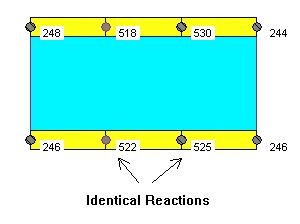
This approach will provide no variation in the point loads on the transfer slab. In the figure above (Fig. 2), the two point loads at the middle are identical, regardless of the supporting conditions below.
 This approach is commonly used, and it is considered more conservative. Its shortcoming is that the load distribution is uniform, ignoring the influence of the structure itself. The point loads on the transfer slab are internal forces in the columns above, and their magnitude is affected by the relative stiffness of all structural elements. However, treating the transfer slab independently and ignoring the rest of the structure is a more conservative analytical approach.
We will follow through with a numerical example to illustrate the major points. If we used R/C BUILDING software and if we set all columns on the transfer slab to have a "footing" support, we can obtain the same results as the tributary area method. (Fig. 3)
Strategy 2: Evaluation of Transfer Loading by 3D Frame Static Analysis

 We can analyze the structure using 1st order static analysis in 3D using R/C BUILDING software, or any other frame analysis software. (Fig. 1) The point loads on the transfer slab will be different from the Tributary Area Method. In this case, the reaction in the transfer column (point load on the transfer slab) is reduced significantly, and the loading is distributed onto the surrounding columns. (Fig. 4)This is because the transfer column is supported by a beam, which only provides an elastic support. In this example, we used a 400mm deep beam. If the beam depth is reduced to as,y 300mm or 200mm, the transfer column reaction will be even smaller. However, the total load will remain the same, but it will be distributed differently.
The bending moment results in the transfer beam are shown in Fig. 5. We can observe that the smaller point load of 348 kN will generate relatively small bending moments in the beam.
Strategy 3: "Very Stiff" Transfer Slab
 We can make the transfer slab and the beams "very stiff" by assigning a different material property, say 100 times greater modulus of elasticity. This will make the transfer floor much stiffer in comparison to the rest of the structure, and it will "enforce" an even distribution of the column reactions. (Fig. 6)
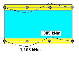
The introduction of a "Very Stiff" beam will have a similar effect on the reactions as the Tributary Area method. However this will also have an effect on the bending moments in the beam. (Fig 7). The moment magnitude will increase, and more importantly we may observe that the negative moment at the column on the right is "lost". This is due to the elastic shortening (squashing) of the columns below, the columns supporting the transfer slabs.
Strategy 4: "Very Stiff" Transfer Beam and Prevented Axial Shortening of Columns Below
In addition to the "Very Stiff" beam, we can introduce an increased axial stiffness of all columns, which includes the columns below the transfer slab. In R/C BUILDING software, there is a global switch that will increase the axial stiffness of all columns by 100 or 10,000 times. In this example, we will increase the axial stiffness of the columns by 10,000 times. It is important to note that we do not increase the column's bending stiffness, so the column below will not influence the bending of the transfer beam.
In this case, the reactions (column loads) will still be identical (Fig. 8)
 and No change in Column Axial Stiffness") In this case, the bending moments will have the expected shape (Fig. 9), but the moment magnitude has increased in comparison to the Elastic Analysis with no increased stiffness, Strategy 2. This is expected since the load is larger and the transfer beam has increased stiffness, and therefore attracts larger internal forces. We may say in this case the beam moments are "more conservative".
In this case, the bending moments will have the expected shape (Fig. 9), but the moment magnitude has increased in comparison to the Elastic Analysis with no increased stiffness, Strategy 2. This is expected since the load is larger and the transfer beam has increased stiffness, and therefore attracts larger internal forces. We may say in this case the beam moments are "more conservative".
Now we can say that we have "forced" the column reactions on the transfer slabs to be uniform, i.e. to mimic the Tributary Area method, and we have increased the bending moments in the transfer beam, as it is working by itself, i.e. as it is analyzed as a two-span continuous beam ignoring the rest of the structure.
The increased axial stiffness of the columns will affect the lateral stability analysis. It will provide un-realistically smaller lateral deflections. When the axial stiffness of the columns is increased, the model cannot be used in lateral stability assessment.
End Notes and Recommendations
The above example illustrates how we can "force" a structural model to behave in a certain manner by assigning increased stiffness to selected element groups. The increase of the bending stiffness of the transfer beam/slab by 100 times, and the axial stiffness of the column by 10,000 shows that we can obtain similar results as the hand calculations, using Tributary Area methods and a simple two-span beam.
We must note that this drastic increase in the stiffness of selected element groups "distorts" the structural model, and might result in an unrealistic and unpredictable distribution of the internal forces, and has to be used very cautiously. Our suggestion is to use the middle ground. This can be achieved by assigning a small increase in the transfer beam/slabs bending stiffness by using a factor of 4 for the modulus of elasticity, and no axial stiffness increase of the columns. The results are shown in Fig. 10 below.
This approach distributes the column loads on the transfer floor more evenly, but not identical as in the Tributary Area Method. The mid-span beam moment (below the transfer column) is also kept relatively large. This approach will probably yield safer but economical designs of the transfer floors.