Components of Dams | Functions of Components of Dams

Dam Components and Parts
Main Dam
This is the main structure built across the river. The height of a dam depends upon desired storage capacity and the site conditions. The crest length of the dam depends upon the topography at the dam site. The barrier may be built of many different materials. The stored water is released from the dam as per requirements.
Flanks/Abutment:
The rock mass on the right & left banks of the river constitutes abutments. Dam is joined with and supported by the abutments. In addition, outlet tunnels, diversion tunnels, and spillways are also placed in the flanks. The geology of the abutments has to be strong enough to enable placing various structural components without any risk. In addition, abutments need to be of competent rock without any structural defects and the lowest permeability
Saddle Dam:
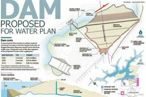
The reservoir is usually formed by the main dam on one side and low/high hills on all other sides of the reservoir. In most cases, the elevation of the hills along the rim of the dam is much higher than the reservoir's maximum water level. In some other cases, elevations of surrounding hills along a part of the rim/periphery of the reservoir are not high enough over a small section to completely contain the stored water, and a saddle (low-level place) is formed. Water can flow out through the saddle. A small embankment is then constructed at this low/saddle point to seal off the reservoir rim and is called a saddle dam. Example: Sukian Dam and Jari Dam for Mangla Dam project.
Diversion Channel/Tunnel
These channel or tunnel are constructed prior to dam construction such that river flow is passed around and away from the dam site through the diversion tunnels and that than dam site remain dry and accessible to construction at all time. The capacity of the diversion structure is set such that most probable floods likely to occur during the construction period can be passed over without the danger of overtopping of cofferdam and inundation of construction area. Necessary arrangements are made at the d/s end for energy dissipation. These tunnels may be abandoned (plugged – Simly dam) after project completion or converted to irrigation/power / desilting tunnels. A diversion tunnel may not be provided (Mirani dam) and u/s coffer dam.
Cofferdam
These are small temporary dams built u/s and d/s of the dam site to make the construction area dry and workable. The u/s cofferdam causes water to flow through the diversion tunnel and the d/s cofferdam prevents the backwater level to inundate the construction area. Cofferdam may be dovetailed in the u/s part of the dam (Mangla) or abandoned. The material used is earth, rock, concrete, etc. Arrangements are required for control of seepage across the coffer dam.
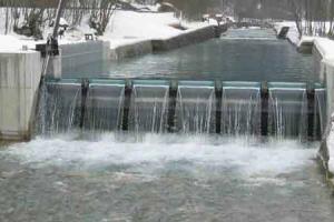
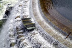
Spillway
This is a water release/conveyance structure to pass the large flood volumes safely across the dam without the danger of overtopping the dam crest. There would be one or more spillways usually at different levels (Service, additional, emergency). The lower spillway is used to release often occurring floods and regular inflows and is called a service spillway. It has usually more elaborate arrangements and may be free-flowing or gated. The auxiliary or emergency spillway is set at or above normal conservation level and has fewer arrangements and is usually free-flowing. This is used only during flood events of extraordinary nature. Fuse plug, rubber dam, etc may be used to delay water release and possibly additional storage at the reservoir.
The spillway may be an integral part of the main dam (mostly for concrete dams) or be a separate structure in the dam abutments.
Outlet Works
- Intake Structure / Tower: This is a structure to admit and control the flow of water into the irrigation/power outlets. It would be a tower or inlet flush with reservoir side walls. Gates may be provided at the u/s, intermediate, or d/s end of the outlet tunnel. Necessary provision is made to keep the intake operation for long after sedimentation by having multiple water entry levels, particularly for domestic supply purposes. Multi-level inlet openings may be used.
- Irrigation/Power Outlet Tunnel: This is a large water conveyance structure to release water to irrigation networks and/or powerhouse turbines. The outlet is in the form of a tunnel dug or formed through the abutment/flank for earth/rockfill dams or through the dam body for a concrete dam. At the u/s end an intake is provided along with gates, and a trash rack. The tunnel design must eliminate the risk of cavitation and/or aeration. Gates may be placed at u/s, d/s, or intermediate locations. The power tunnel is transitioned into a surge chamber, penstock/scroll case, etc. Energy dissipation structure may be provided at the d/s end if needed. Irrigation outlets may release into a canal or river if the demand site is at a distance from the dam. The intake level of the tunnel is kept below or at the dead storage level. An air vent is provided to minimize cavitation. Water cushions for vortex control are also provided.
- Low-Level Outlet: A low outlet tunnel may be provided to flush sediments, draw water from below dead storage level under very drought conditions, emptying of reservoirs in emergencies, draw water during repair of outlet tunnel/gates, etc. The intake level is kept much lower than the intake level main irrigation tunnel. May discharge into stilling basin for spillways/outlet works or as a separate energy dissipation structure provided. [Similar to under sluices in a barrage.]
- Gates/Valves/
- Trash Rack, air duct for cavitation control
Drainage System
Dams are designed to store water with the least seepage through the dam embankment and the foundation but seepage does occur. The drainage/seepage water also causes tremendous uplift pressure, particularly at the d/s half of the dam base. Certain features are included in the dam design to minimize seepage through the foundation and through the dam embankment and uplift pressure. Cutoff wall, sheet piles, slurry trench, etc.
- Grout Certain: An impermeable zone is created under the dam.
- Grout Blanket: Impermeable area is created u/s of the dam.
- Pressure relief / Drainage Wells: Wells are installed at the d/s area to pick and remove seepage water to reduce uplift pressure in the
- Drainage gallery foundation area: A horizontal/inclined gallery is formed in the body of the dam (especially in concrete dams) where water from drainage wells discharges into and ultimately flows out of the dam body. It also intercepts leaks through the dam body.
- Horizontal Blanket Drain: To intercept seepage lines at the base of the dam on the d/s side.
- Chimney Drain:
- Toe Drain: Vertical or inclined drainage filter layer (usually d/s of the impermeable clay core) to intercept seepage flow. A drain is provided at the toe of the dam (homogeneous coarse fill) to intercept seepage flow inside the dam body.
Preliminary Works
- Trench provided at d/s of the dam to intercept seepage flow lines. gradient and seepage rate.
- D/S Trench: Impermeableblanket to lengthen the seepage path and lower hydraulic
- Civil works, infrastructures, and buildings are required to be provided before the start of construction of the main dam work. These include offices, staff housing, community buildings, water supply, approach road, client/consultant/contractor camp, labor camp, security arrangements, rest house, rail sidings, airstrip, hele-pad, etc.
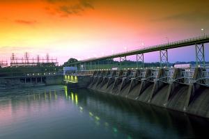
Hydropower Development
- Powerhouse: Building to house turbine, generators, mechanical workshop, valves, draft tube, office, control room, visitor area, up transformer, etc for hydropower generation.
- Penstock: This is a large-diameter pressure pipe used to deliver water to turbines.
- Surge chamber: To contain water hammer surge on plant load rejection / sudden shut-down.
- Switchyard: This is an area to install electrical equipment to change low to high tension power supply for further transmission.
Slope Protection/Riprap
Stone is placed on u/s & d/s dam slopes for protection against damage due to wave action, rainwater, and burrowing animals. Parapet walls may be used to protect the dam top against sudden waves generated by strong winds, tsunamis, etc.
Dam Instrumentation
Various gages/instruments are installed in the dam body, foundations, and spillway to monitor settlement, movement, stresses, pore water/uplift pressure, and earthquake.
Stilling Basin
To dissipate excess energy of diversion tunnel, low-level outlet, irrigation tunnel, spillway, etc.
Gallery/Shafts
These are provided in the dam body for access to the interior of the concrete dam body. These are horizontal, vertical (with round stairways), and sloping.
Operational buildings
These are buildings required for the operation of the dam and works. These include Office buildings, Rest Houses, Security buildings, Staff residences and other community buildings, and gate control rooms.
Temporary works:
These are installations required for temporary use and are removed after project completion. These include contractors camp, material processing, handling and stock area, machine room, casting yard, steel fabrication, labor camp, etc.
Core:
It is made up of impervious material and its object is to make the dam water-tight. The particle size of the material used in the core is small so that it can retain water and does not allow further seepage.
Shell:
Shell is made up of pervious material (porous material). It gives strength and support to the core wall. The particle size of the materials used in the shell is large i.e. coarse material.
Transition filters:
As the core contains fine material and the shell contains coarse material so there is a chance that both may get mixed into each other. These filters are installed in the dam body to stop the mixing of materials from either side into each other. Transition filters are made of a material that is semi-pervious in nature.
Cut-off trench:
It is a trench dug to fill it with impervious material e.g. Rich Concrete
Sheet pile wall:
A sheet pile wall is used in areas where it is required to stop water from flowing across. OR when the impervious layer is at very depth and if the trench cannot be drugged out due to economic constraints then this sheet pile wall is used.
Impervious stream blanket:
An impervious stream blanket is laid in the foundation of the dam and its objective is to stop the seepage in the dam foundation.
Rip rap:
This material basically belongs to the category of geotextiles and is used to stop upstream face from erosion. It is made up of large stones which range from 1/2 m - 1 m.
Horizontal Drainage:
It is usually used if the dam body is made of impervious material. The dam body may contain moisture already or due to very loss seepage, If this water remains in the dam body, pore water pressure is developed and effective pressure is reduced, so to remove that water this zone is used.
Soil turfing / Sod:
To avoid erosion due to rain, snowfall, wind, etc. soil turfing is used. It is also called sod.
Crest/top:
It is the upper part of the dam which divides the upstream face and the downstream face. Its objective is to give access to vehicles over it.
Freeboard:
To avoid overtopping the dam, a freeboard is used.