Rankine's Assumptions for Earth Pressure Theory for Active/Passive Pressure
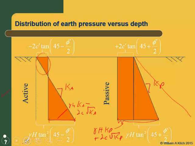
Rankine's Theory for Earth pressure
As originally proposed, Rankine's theory is applied to uniform cohesion-less soil only. Later it was extended to include cohesive soil by Bell in 1915.
Assumptions of Rankine's theory:
Rankine approached the lateral earth pressure problem with the following assumptions:
- The soil is homogeneous and isotropic, which means c, φ and γ have the same values everywhere, and they have the same values in all directions at every point (i.e., the strength on a vertical plane is the same as that on a horizontal plane). This discussion will be expanded later to consider layered soils, where each layer has different values of c, φ and γ∙
- The most critical shear surface is a plane. In reality, it is slightly concave up, but this is a reasonable assumption (especially for the active case) and it simplifies the analysis.
- The ground surface is a plane (although it does not necessarily need to be level).
- The wall is infinitely long so that the problem may be analyzed in only two dimensions. Geotechnical engineers refer to this as a plane strain condition.
- The wall moves sufficiently to develop the active or passive condition.
- The resultant of the normal and shear forces that act on the back of the wall is inclined at an angle parallel to the ground surface (Coulomb's theory provides a more accurate model of shear forces acting on the wall).
Active Condition
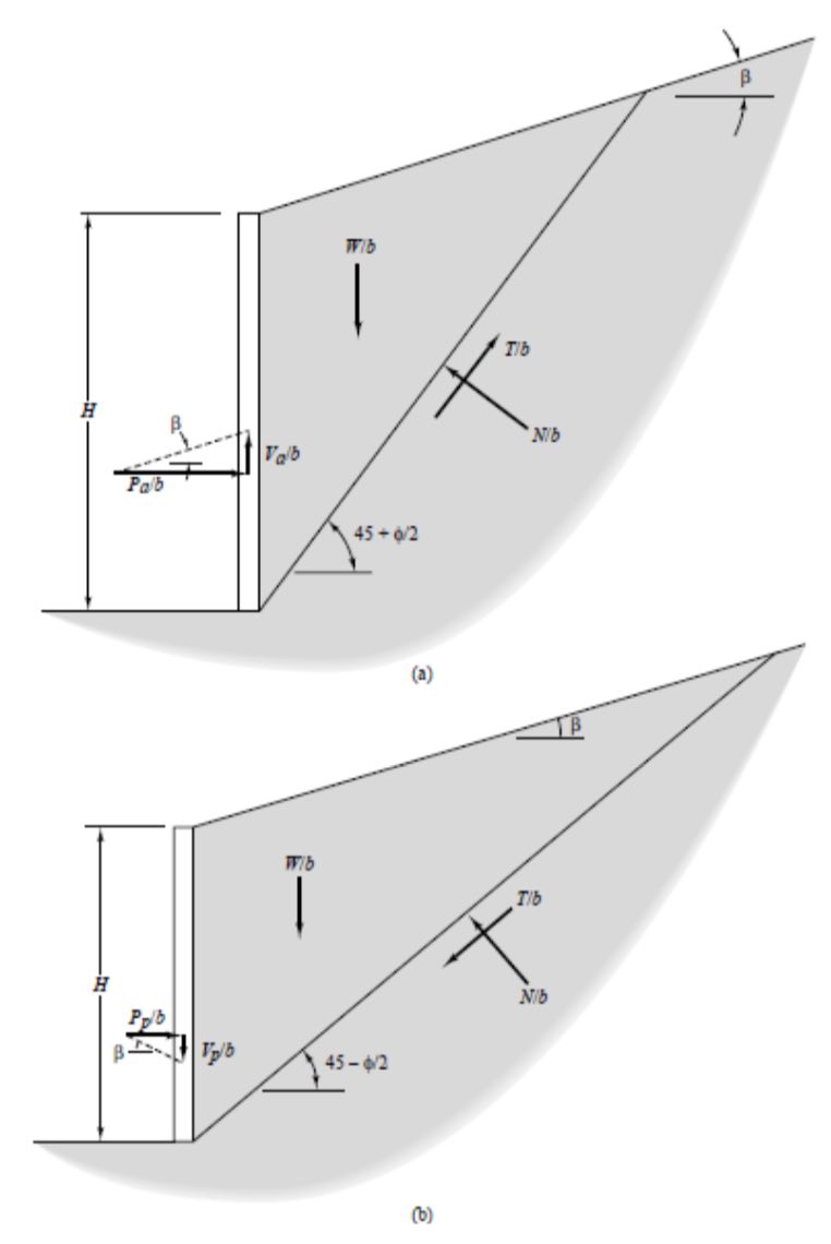
With these assumptions, we can treat the wedge of soil behind the wall as a free body and evaluate the problem using the principles of statics, as shown in Figure 1a. This is similar to methods used to analyze the stability of earth slopes, and is known as a limit equilibrium analysis, which means that we consider the conditions that would exist if the soil along the base of the failure wedge was about to fail in shear. Weak seams or other non-uniformities in the soil may control the inclination of the critical shear surface. However, if the soil is homogeneous, Pa/b is greatest when this surface is inclined at an angle of 45 + φ/2 degrees from the horizontal, as shown in the Mohr's circle. Thus, this is the most critical angle.
Solving this free body diagram for Pa/b and Va/b gives:
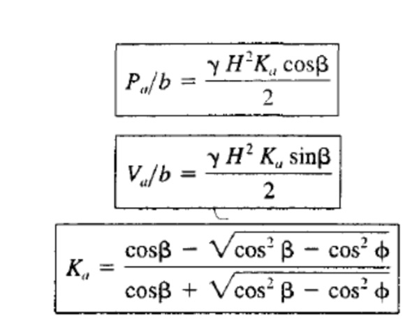
The magnitude of Ka is usually between 0.2 and 0.9. Equation is valid only when β ≤ φ. If β= 0, it reduces to:
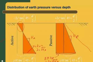
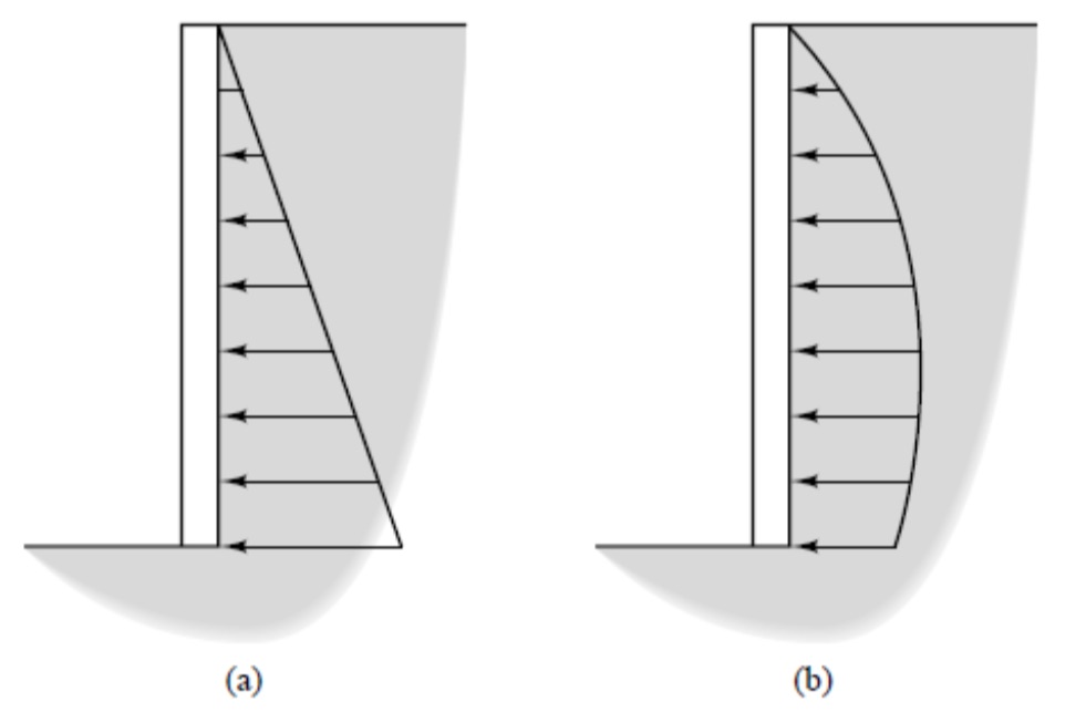
A solution of Pa/b as a function of H would show that the theoretical pressure distribution is triangular. Therefore, the theoretical pressure and shear stress acting against the wall, α and τ, respectively, are:
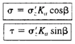
Where;
σ = soil pressure imparted on retaining wall from the soil
τ = shear stress imparted on retaining wall from the soil
Pa/b = normal force between soil and wall per unit length of wall
Va/b = shear force between soil and wall per unit length of wall
b = unit length of wall (usually 1 ft or 1 m)
Ka = active coefficient of lateral earth pressureσz' = vertical effective stress
β = inclination of ground surface above the wall
H = wall height
However, observations and measurements from real retaining structures indicate that the true pressure distribution, as shown in Figure 2, is not triangular. This difference is because of wall deflections, arching, and other factors. The magnitudes of Pa/b and Va/b are approximately correct, but the resultant acts at about 0.40H from the bottom, not 0.33H as predicted by theory (Duncan et al., 1990).
Passive Condition
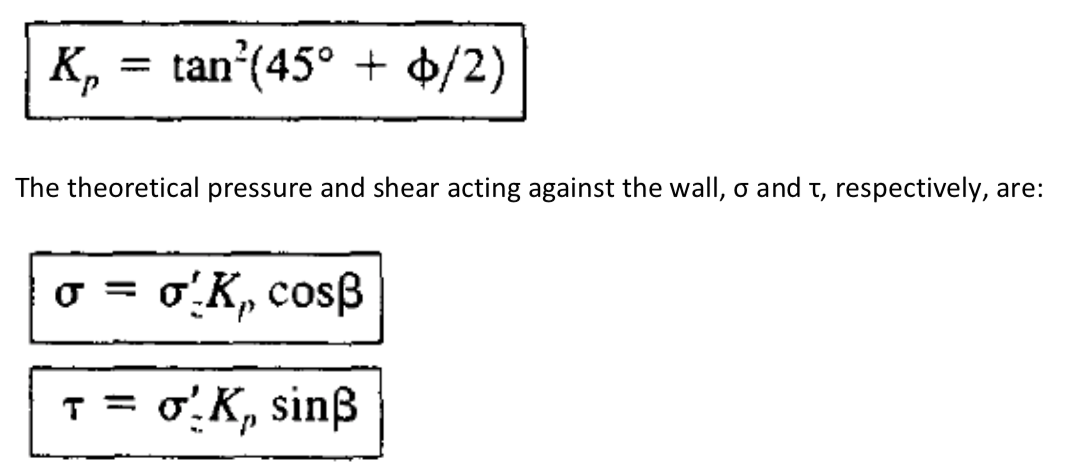
Rankine analyzed the passive condition in a fashion similar to the active condition except that the shear force acting along the base of the wedge now acts in the opposite direction (it always opposes the movement of the wedge) and the free body diagram becomes as shown in Figure 1b. Notice that the failure wedge is much flatter than it was in the active case and the critical angle is now 45 – φ/2 degrees from the horizontal. The normal and shear forces, Pp/b and Vp/b, respectively, acting on the wall in the passive case are:
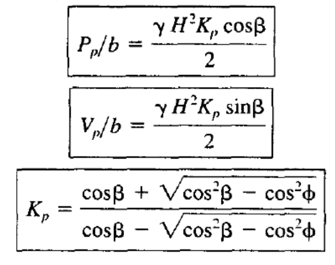
Equation is valid only when β≤ φ. If β = 0, it reduces to:
