Unconfined Compression Test - UC Test

Purpose:
The primary purpose of Unconfined Compression Test is to determine the unconfined compressive strength, which is then used to calculate the unconsolidated undrained shear strength of the clay under unconfined conditions. According to the ASTM standard, the unconfined compressive strength (qu) is defined as the compressive stress at which an unconfined cylindrical specimen of soil will fail in a simple compression test. In addition, in this test method, the unconfined compression strength is taken as the maximum load attained per unit area, or the load per unit area at 15% axial strain, whichever occurs first during the performance of a test.
Standard Reference:
ASTM D 2166 - Standard Test Method for Unconfined Compressive Strength of Cohesive Soil
Significance:
For soils, the undrained shear strength (su) is necessary for the determination of the bearing capacity of foundations, dams, etc. The undrained shear strength (su) of clays is commonly determined from an unconfined compression test. The undrained shear strength (su) of a cohesive soil is equal to one half the unconfined compression strength (qu) when the soil is under the f = 0 condition (f = the angle of internal friction). The most critical condition for the soil usually occurs immediately after construction, which represents undrained conditions, when the undrained shear strength is basically equal to the cohesion (c). This is expressed as:
Then, as time passes, the pore water in the soil slowly dissipates, and the intergranular stress increases, so that the drained shear strength (s), given by s = c + s‘tan f , must be used. Where s‘ = intergranular pressure acting perpendicular to the shear plane; and s‘ = (s - u), s = total pressure, and u = pore water pressure; c’ and φ’ are drained shear strength parameters. The determination of drained shear strength parameters is given in Experiment 14
Equipment:
Compression device, Load and deformation dial gauges, Sample trimming equipment, Balance, Moisture can.
Unconfined Compression Test Procedure:
- Extrude the soil sample from Shelby tube sampler. Cut a soil specimen so that the ratio (L/d) is approximately between 2 and 2.5.
Where L and d are the length and diameter of soil specimen, respectively. - Measure the exact diameter of the top of the specimen at three locations 120° apart, and then make the same measurements on the bottom of the specimen. Average the measurements and record the average as the diameter on the data sheet.
- Measure the exact length of the specimen at three locations 120° apart, and then average the measurements and record the average as the length on the data sheet.
- Weigh the sample and record the mass on the data sheet.
- Calculate the deformation (∆L) corresponding to 15% strain (ε).
Where L0 = Original specimen length (as measured in step 3). - Carefully place the specimen in the compression device and center it on the bottom plate. Adjust the device so that the upper plate just makes contact with the specimen and set the load and deformation dials to zero.
- Apply the load so that the device produces an axial strain at a rate of 0.5% to 2.0% per minute, and then record the load and deformation dial readings on the data sheet at every 20 to 50 divisions on deformation the dial.
- Keep applying the load until (1) the load (load dial) decreases on the specimen significantly, (2) the load holds constant for at least four deformation dial readings, or (3) the deformation is significantly past the 15% strain that was determined in step 5.
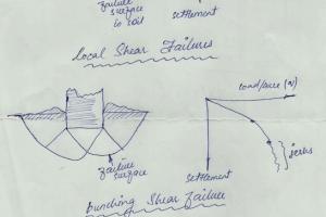
- Draw a sketch to depict the sample failure.
- Remove the sample from the compression device and obtain a sample for water content determination. Determine the water content.
Unconfined Compression Test Analysis:
- Convert the dial readings to the appropriate load and length units, and enter these values on the data sheet in the deformation and total load columns. (Confirm that the conversion is done correctly, particularly proving dial gauge readings conversion into load)
- Compute the sample cross-sectional area
- Compute the strain
- Computed the corrected area,
- Using A’, compute the specimen stress,
- Compute the water content, w%.
- Plot the stress versus strain. Show qu as the peak stress (or at 15% strain) of the test. Be sure that the strain is plotted on the abscissa. See example data.
- Draw Mohr’s circle using qu from the last step and show the undrained shear strength, su = c (or cohesion) = qu/2. See the example data.