Factors Affecting Construction of Tunnels

Why Tunnels are Constructed:
- To meet the requirements of rapid transportation in big cities
- To connect by shortest route, two termination separated by mountain
- To reduce very steep grades
- To avoid the excessive cost of maintenance of an open cut subjected to land slides or snow drifts
- To avoid the expensive acquisition of valuable built up land, tearing up pavements and holding up traffic for long periods in large cities
- When the depth of ordinary cutting exceeds 20m and the ground rises rapidly for a considerable distance after wards
Factors affecting location of a tunnel:
- If should follow the best line adopted to the proposed traffic.
- If should be most economical in construction an operation.
- Convenience Ingress (enter) and Egress (leave)
Surveying Steps in Tunnels:
- Surface Survey
- Transferring the alignment under ground
- Transferring levels under ground
1. Surface Survey:
This includes:
- A preliminary survey by transit and staid for 2-3miles (3-4km) on either side of the proposed alignment.
- A plan (map) with a scale of say 1 in with contours drawn at 5m (20) intervals.
- Final alignment is selected form this plan.
- A detail survey of the geological information of strata as the cost of tunneling depends upon the nature of materials to be encountered.
The proposed route having been decided upon, the following points require consideration.
- Alignment of the centre line of the tunnel.
- Gradient to be adopted.
- Determination of the exact length of tunnel.
- Establishment of permanent stations marking the line.
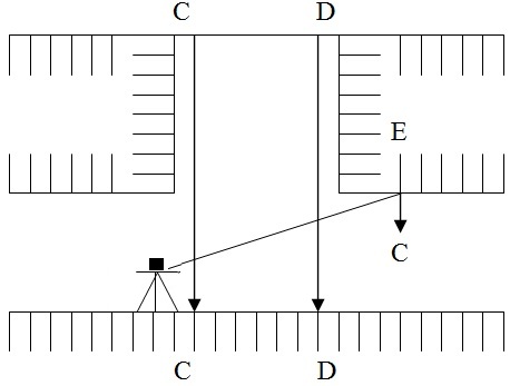
Control surveys for tunnel layouts are performed on the surface joining the terminal points of the tunnel is shown in figure (1).
2. Transferring the alignment underground
 This is the most difficult and important operation in setting out a tunnel.
- Fix two timber beams C and D as shown in figure two across the top of the shaft near its edges perpendicular to the direction of tunnel and as far apart as possible.
- A threadlike is set up at a ground at a pre-determined station on a centre. Line mark one ground surface and another stations is again on the centre line itself.
- The centre line is very carefully set up on the beams preferably on the plates fixed on a beam and drilled with hole for suspending wires by repetition observing and averaging the result.
- From these pts two long penal wire with heavy plumb hobs 10 to 15 kg attacked to their lower edges or suspended down the shaft.
- At the bottom these plumb bobs are immured in bucket of water, oil etc to eliminate oscillation.
- Great care must be taken that wires and plumb bobs are hanging free. As a check the dist b/w the wires at the top and at the bottom of the shaft is to be measured and this should be the same.
- The line joining the two wires gives the dir of alignment under ground.
- The theologize is transfer to the bottom of shaft and through the no of trails suspended wires.
- Now the alignment is marked on marks driven into the whole i.e, E drilled on the roof.
3. Transferring levels underground:
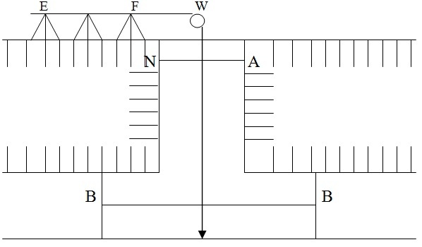 Leveling on the surface is done in the usual way and the levels are transfer underground at the ends of the tunnel from the nearest bench mark. In case of transfer of levels underground at the shaft. The steps involve are
- A fine steel wire loaded with weight of 5 to 15 kg is passed over a pulley (w) at the top of the shaft and is lowered into the shaft as shown in fig.3
- Tow fine wire AA and BB horizontally stretched at the top and bottom of the shaft rasp.
- The steel wired lowered into the shaft is so adjusted that it is in contact with both the wires AA and BB.
- The pts of contact are marked on a still wire by a piece of chalk or by some other marker.
- The wire is withdrawn form the shaft and is stretched on the ground.
- The dist b/t the two marks on he wire is measured using the measuring tape and this gives the level of the bottom of the shaft.
Also See: Levelling Equipment
Latitude & Longitude
O = Centre of earth
N = North Pole
S = South Pole
Nos = Polar axis or polar diameter about which earth rotates.
A = Any point on surface of earth
The position of a place on the earth surface is specified by latitude and longitude. The semi circle ‘NAS’ passing through A and terminates by the Poles N and S is called Meridian of the place.
Latitude:
Latitude of a place is the angular distance measured from the equator towards the nearer Pole along the meridian of the place or latitude of any pt ‘A’ is angle or arc AA’’. Latitude can also be defined as the angular distance that the place is north or south of equator.
The earth sphere being divided into two hemispheres by the equator, the upper one containing the North Pole is called the northern hemisphere. While the lower one having the South Pole is called southern hemisphere. The place is said to have a north latitude if it is in the northern hemisphere and south latitude if it is in the southern hemisphere. The latitude angle is measured (90) at the earth center. North or south from the equatorial plane. Latitude north of equator is considered positive and that south of equator negative.
Longitude:
Longitude of a place is the angular distance b/t the meridian of a place and the standard prime meridian Or Longitude of any place ‘A’ is angle ‘LA’ measured in the equatorial plane b/t the standard meridian and the meridian through A. Or The meridian NGS passing through Greenwich England has been adopted internationally as the standard meridian. This meridian divides the sphere into two hemispheres. The longitude is measured from “O” to 180 either towards east or west. The west longitude is considered as positive and the east as negative. Longitude angles are measured at the earth centre east or west from the plane of ‘O’ longitude which has been arbitrary placed through green witch England.
Hence the position of place ‘A’ is completely specified by the latitude and longitude. These two terms give unique location of any pt on the earth. This system of geographic co-ordinates is used in navigation and Geodesy.