Highway Drainage Design, Structures and Guidelines

Highway Drainage includes collecting, transporting, and disposing of surface/subsurface water originating on or near the highway right of way or flowing in streams crossing bordering that right of way. Drainage of highway is important because water damage highway structure in many ways. The water which are dangerous for highways are:
Rainwater: Cause erosion on surface or may seep downward and damage pavement (surface drains)
Groundwater: May rise by capillary action and damage pavement (sub-surface damage)
Water body: May cross a road (river/stream) and may damage road (cross drainage works)
It is more appropriate to take care of drainage at the time of location survey. Ideal location fro a drainage stand point would lie along the divides b/w large drainage areas. Then all streams flow away from the highway, and the drainage problem is reduced to caring for the water that falls on the roadway and back slope. In contrast location paralleling large streams is far less desirable as they cross every tributary where it is largest. Ideal locations avoid steep grades and heavy cuts and fills as they create difficult problems in erosion control.
Surface Drainage of Highways - Surface runoff
Draining the roadway and road side:
Pavement and shoulder
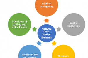
 The highway engineer should ensure that the precipitation is removed from the pavement as soon as possible and that highway drainage is done efficiently. Water that falls on the road way follows laterally or obliquely from it, under the influence of cross slope. Or super elevation in pavement and shoulder. A suitable value of cross fall for paved roads is about 3% for carriage way with a slope of 4-6% for shoulders. And increased cross fall for the carriage way e.g. 4% is desirable if the quantity of the final shape of the road surface is likely to be low for any reason,
Drainage with pavement layers:
Is an essential element of structural design because the strength of the subgrade used for design purposes depends on the moisture content during the most likely adverse conditions. It is evident that benefits are derived from applying steeper cross falls to layers at successive depths in the pavement.
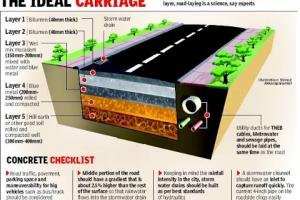
The top of the sub-base should have a cross fall of 3-4% and the top of the sub-grade should be 4-5%. These cross falls not only improve the drainage performance of the various layers, but also provide a slightly greater thickness of material at the edge of pavement where the structure is more vulnerable to damage. The design thickness should be that at the center line of the pavement.
Road way drainage in fill:
Most common practice is to let the flow continue of the shoulder and down the slope to the natural ground. Little erosion, if slopes are protected by turf or if the water flows across the roadway and down the slope as a sheet.
- Unprotected slopes wash badly
- Irregularities in shoulder or pavement concentrate water into small streams causing erosion e.g. at low points of sag.
- One way of preventing washing of side slope is to retain the water at the outer edge of shoulder.
Highway drainage of run off in cut:
Water from traveled way and back slope is collected in road side channel, trapezoidal or triangular.
- Design is based on slow to be accommodated.
- Intercepting channel (sometimes called crown ditch) may be employed at the top of cut slope.
Advantages of Highway drainage in cut
- It prevents erosion of the back slope by runoff from the hill above.
- it intercepts water, not allowing it to enter side drain which may cause greater discharge in side drains.
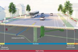
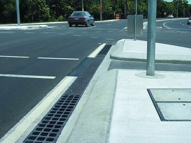
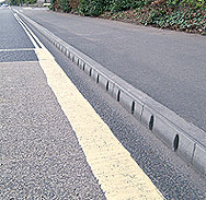
Road-way drainage in urban areas:
Water falling on the road surface generally flows along the gutter to curbs or gutter inlets and from them to underground storm drains.
- Expensive as compared to rural area drainage works.
- We have certain justification i.e. large volume of traffic, pedestrian’s property.
- Designed to limit the spread of water over the traveled lanes to some arbitrary maximum.
- Inlets at low points should be designed for longer return period.
Highway runoff drainage in rural areas:
Generally open unlined drains with suitable x-section and longitudinal slope are provided parallel to road alignment, called longitudinal drains. In embankment they are provided on one or both side beyond the toe. In cutting area it is installed on either side of formation. Construction of deep open drains may be undesirable (restriction of space). In such cases covered drains or drainage trenches properly filled with layers of coarse sand and gravel may be used.
Cross Drainage Structures & Works
When a low laying areas or a stream or a river crosses the alignment of road, arrangements should be made to allow the water of stream or river to pass on the other side of road. The water is passed by structures known as cross drainage works. These include road culverts, bridge and cause ways.
1. Culverts:
Encompasses practically all closed conduits employed fro highway drainage with the exception of storm drains (covered pipes in urban area)
- [B.S.S](a) A drain sewer or water covers totally enclosed and usually of a size through which a man can pass.
- (b) An opening through on embankment for the conveyance of water by mean of pipe or an enclosed channel.
2. Bridges:
Bridges are used in runoff drainage systems where stream span is large, for which special designs are made almost in every case > 6m.
Common culvert types are;
- Pipe culvert
- Arch pipe culvert
- Box culvert
- Bridge culvert
- Arch culvert
3. Cut off walls:
Extending below the level of expected scour.
- Culverts are usually installed in the original stream bed with their grades confirming to those of natural channel. In this way distribution to stream flow and the erosion problem it create are held to minimum.
4. Dips or cause ways in Highway Drainage:
A dip is formed by lowering the roadway grade to the level of the stream from the bank to bank of the stream. Vertical curves at each end transition back to the regular grade line. Washing of the roadway surface is prevented by curtain wall of concrete rubble masonry. With proper design it is damaged little by flood water, so that maintenance cost are low. With long transition at ends they ride smoothly.
Disadvantage of dips is interruptions and hazard to traffic when the dip is flowing.
5. A dip culvert combined:
(High level causeway) has been sometime employed to grade advantage. Partially lowered pipe culverts under the road surface at stream bed level carry small flows without inconvenience to traffic. The larger waterway capacity of the dip comes into play during major floods.
Sub Surface Highway Drainage
- Sub grade may be damaged by sub soil water.
- Sub soil water as free water, when water table is high or it may come up by capillary action to the subgrade when water table is low.
- Sub-grade should be of self draining material so that it may pass off the percolation water that comes to it to remain dry and stable.
- But if sub-grade is of soft and retentive soil, or there are underground springs bringing free water to the subgrade fro that reason subsurface drains should be constructed about 1 ½’ to 2’ below the formation level to carry away water from the subgrade and thus keep it dry. ( in easily drainable soil water can be lowered by deep or open side drains, it also takes rain water.
- Cross-drains may be in the form of trapezoidal trenches filled with selected rubble called rubbled drains or trench drains.
- Depth is not much and the discharge is small.
- The pipes are surrounded by filler material and the remaining of the cross trench is filled with graded rubble, the bigger size rubble being nearer to the pipe. Water of wet subgrade passes through the open joint of pipes and enter the lateral drain which discharge into the longitudinal drain pipe in the two longitudinal side trenches.
- Longitudinal drain carry water to the nearby stream.
- Cross-drains, staggered in herring bone fashion.
- Spacing of lateral drains is less in impermeable soil and more in permeable soil.
Intercepting drains:
For control of seepage in cuts or side hill locations and for highway Drainage of runoff water