Structural Drawings required for Building Construction

Structural Drawings required for Building Construction
- General Notes
- Typical sections
- Foundation excavation plan
- Footing sections
- Ground floor column plan
- Column sections
- Ground floor plinth beams plan
- Plinth beams sections
- Ground floor beam plan
- Beam sections
- Ground floor slab bottom rebar detail
- Ground floor slab top rebar detail
- Ground floor slab section
- Overhead water tank design
- Septic tank design
General Notes
General notes are typically included on each sheet of the structural drawings and provide important information regarding codes, standards, materials, and construction requirements. They may include information about loadings, concrete mix design, steel grades, reinforcement detailing, and other relevant specifications.
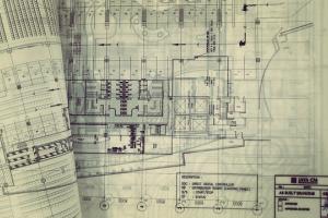
Structural drawings play a crucial role in the construction of a building by providing detailed information about the design and construction of the structural components. Here's an explanation of the specific structural drawings you listed:
Typical Sections:
Typical sections are representations of standard structural elements that occur repeatedly throughout the building. They provide a general understanding of the dimensions, reinforcement details, and connections for columns, beams, slabs, and other key components.
Foundation Excavation Plan:
The foundation excavation plan depicts the outline of the building's foundation, including the dimensions and depths of the excavations. It may also indicate the soil bearing capacity, groundwater level, and any necessary de-watering measures.
Footing Sections:
Footing sections show the construction details of the footings that support the building's columns or walls. They include information about the dimensions, reinforcement layout, concrete cover, and any additional requirements such as dowels or anchor bolts.
Ground Floor Column Plan:
This plan displays the layout and positions of the columns on the ground floor. It indicates the column sizes, spacing, and their relationship to other structural elements and architectural features.
Column Sections:
Column sections provide detailed drawings that illustrate the dimensions, reinforcement, and construction details of the columns. They specify the sizes and types of reinforcing bars, concrete cover, and any additional elements such as column capitals or pedestals.
Ground Floor Plinth Beams Plan:
Plinth beams are horizontal beams that connect the columns at the ground level. The plan shows the layout and positions of these beams, including their dimensions, reinforcement, and any required construction details.
Plinth Beams Sections:
Plinth beam sections provide detailed drawings that highlight the dimensions, reinforcement, and construction requirements of the plinth beams. They specify the sizes and types of reinforcement bars, concrete cover, and any additional elements necessary for proper construction.
Ground Floor Beam Plan:
The beam plan for the ground floor displays the layout and positions of the beams that support the floor slabs. It includes information on beam sizes, spacing, and connections to columns and walls.
Beam Sections:
Beam sections provide detailed drawings that illustrate the dimensions, reinforcement, and construction details of the beams. They specify the sizes and types of reinforcing bars, concrete cover, and any additional elements such as stirrups or shear reinforcement.
Ground Floor Slab Bottom Rebar Detail:
This drawing provides detailed information about the reinforcement layout at the bottom of the ground floor slab. It shows the sizes and spacing of reinforcing bars, distribution of reinforcement, and any additional details such as bar bending schedules.
Ground Floor Slab Top Rebar Detail:
Similar to the bottom rebar detail, this drawing provides information about the reinforcement layout at the top of the ground floor slab. It includes the sizes, spacing, and distribution of reinforcing bars.
Ground Floor Slab Section:
The slab section drawing illustrates the cross-sectional view of the ground floor slab. It shows the thickness of the slab, reinforcement details, and any additional elements such as drop panels or edge beams.
Overhead Water Tank Design:
The overhead water tank design drawing provides detailed information about the design and construction of the water tank, including its capacity, dimensions, reinforcement, and any necessary connections to the building's structural system.
Septic Tank Design:
The septic tank design drawing presents the design and construction details of the septic tank, including its capacity, dimensions, reinforcement, inlet/outlet pipes, and any additional requirements for proper functioning.