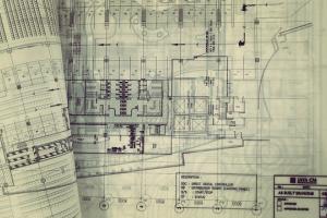
Electrification Drawings Required in Building


List of Electrification drawings
Electrification drawings are a set of technical diagrams and plans that depict the electrical systems and infrastructure within a building or facility. These drawings provide detailed information about the placement, connections, and specifications of electrical components, equipment, and wiring. Here's an explanation of the various types of electrification drawings listed:
- Electrical Legend
- Floor Lighting Plan
- Floor Power Plan
- Single Line Diagram
- Fire Alarm Layout
- Floor Sound System and CCTV Camera
- Equivalency Chart
- Lightening Protection Earthing Details
1. Electrical Legend:
An electrical legend is a key or guide that explains the symbols, abbreviations, and notations used in electrification drawings. It helps users understand the representation of different electrical elements and their meanings.
2. Floor Lighting Plan:
This drawing illustrates the layout and placement of lighting fixtures, switches, and controls on a specific floor of a building. It provides details about the types of lights, their locations, and any specific lighting design considerations. This is the drawing of the lights to be installed in the building. the lights should be placed in such a way that they cover most of the area of the room as well as a flash in the eyes of the occupants.
3. Floor Power Plan:
The floor power plan showcases the distribution of electrical power outlets, sockets, and circuits within a floor. It indicates the positions of power panels, switches, outlets, and other power-related infrastructure, ensuring a comprehensive electrical supply throughout the area.
4. Single Line Diagram:
A single-line diagram (SLD) is a simplified representation of an electrical system, showing all major electrical components, such as generators, transformers, breakers, and loads, in a single-line format. It provides an overview of the system's architecture and helps understand the flow of electricity.
5. Fire Alarm Layout:
This drawing presents the arrangement and positioning of fire alarm devices, such as smoke detectors, heat detectors, fire alarm control panels, and notification appliances, within a building. It ensures proper coverage and functioning of the fire detection and alarm system.
6. Floor Sound System and CCTV Camera:
This drawing depicts the placement and connections of speakers, amplifiers, microphones, and other components of a sound system within a floor. It may also include the location and coverage areas of closed-circuit television (CCTV) cameras for security purposes.
7. Equivalency Chart:
An equivalency chart provides a comparison of different electrical standards, codes, and regulations. It helps in ensuring compliance with specific requirements and allows for easy reference when working with international or regional variations.
8. Lightning Protection Earthing Details:
This drawing provides information about the earthing system and grounding arrangements designed to protect the building from lightning strikes. It includes details of conductors, electrodes, grounding rods, and connections to divert lightning energy safely into the ground.
These electrification drawings collectively offer a comprehensive understanding of the electrical infrastructure, systems, and safety measures within a building. They serve as essential references for electrical engineers, architects, contractors, and other professionals involved in the design, installation, and maintenance of electrical systems.