Reverse or Ogee Curve - Definition and Making

Curves have always been revered for their ability to add grace and sophistication to any structure. Among the various types of curves, one that stands out for its unique aesthetic appeal and practical applications is the reverse or ogee curve. With its distinctive S-shaped profile, the reverse curve combines elegance with functionality, making it a popular choice in both traditional and contemporary designs.
Definition:
Combination of two or more simple circular curves of different radii having their curvature in the same direction. Essentially, a compound curve consists of two curves that are joined at a point of tangency and are located on the same side of a common tangent. Though their radii are in the same direction, they are of different values.
Applications of Ogee Curve in Transportation Engineering
Beyond bridges and dams, the reverse curve has also found its way into the field of highway design. In road engineering, the reverse curve is commonly used to enhance safety and driver comfort. By introducing a reverse curve at critical locations, such as sharp turns or intersections, engineers can improve the transition between different alignment sections. This design feature reduces the risk of accidents, as drivers can navigate the curve more smoothly and with better visibility.
Moreover, the reverse curve has proven beneficial in reducing vehicle speeds on highways. The S-shaped profile adds a visual element that captures drivers' attention, causing them to naturally slow down as they approach the curve. This helps enhance road safety by minimizing the likelihood of accidents due to excessive speed.
REVERSE OR OGEE CURVE - Making & Methodology
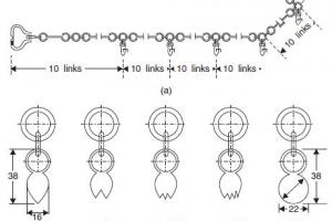
 This is the process of establishing the center line of the curve on the ground by means of pegs at 10-m to 30-m intervals. In order to do this the tangent and intersection points must first be fixed in the ground, in their correct positions.
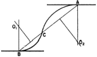
Consider Figure 8.3. The straights 0I1, I1I2, I2I3, etc., will have been designed on the plan in the first instance. Using railway curves, appropriate curves will now be designed to connect the straights.
The tangent points of these curves will then be fixed, making sure that the tangent lengths are equal, i.e. T1I1 = T2I1 and T3I2 = T4I2. The coordinates of the origin, point 0, and all the intersection points only will now be carefully scaled from the plan. Using these coordinates, the bearings of the straights are computed and, using the tangent lengths on these bearings, the coordinates of the tangent points are also computed. The difference of the bearings of the straights provides the deflection angles (delta) of the curves which, combined with the tangent length, enables computation of the curve radius, through chainage and all setting-out data.
Now the tangent and intersection points are set out from existing control survey stations and the curves ranged between them using the methods detailed below.