Effects of Slope of Chute on Stilling Basin

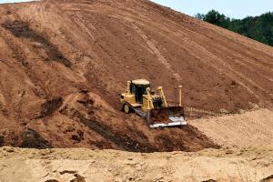
A factor which occasionally affects stilling basin operation is the slope of the chute upstream from the basin. The foregoing experimentation was sufficiently extensive to shed some light on this factor. The tests showed that the slope of chute upstream from the stilling basin was unimportant, as far as jump performance was concerned, provided the velocity distribution in the jet entering the jump was reasonably uniform.
For steep chutes or short flat chutes, the velocity distribution can be considered normal. Difficulty is experienced, however, with long flat chutes where frictional resistance on the bottom and side walls is sufficient to produce a center velocity greatly exceeding that on the bottom or sides.
When this occurs, greater activity results in the center of the stilling basin than at the sides, producing an asymmetrical jump with strong side eddies. This same effect is also witnessed when the angle of divergence of a chute is too great for the water to follow properly.
In either case the surface of the jump is unusually rough and choppy and the position of the front of the jump is not always predictable. When long chutes precede a stilling basin the practice has been to make the upstream portion unusually flat, then increase the slope to 2:1, or that corresponding to the natural trajectory of the jet, immediately preceding the stilling basin.
The most adverse condition has been observed where long canal chutes terminate in stilling basins. A definite improvement can be accomplished in future designs where long flat chutes are involved by utilizing the Type III basin. The baffle piers on the floor tend to alter the asymmetrical jet, resulting in an overall improvement in operation.
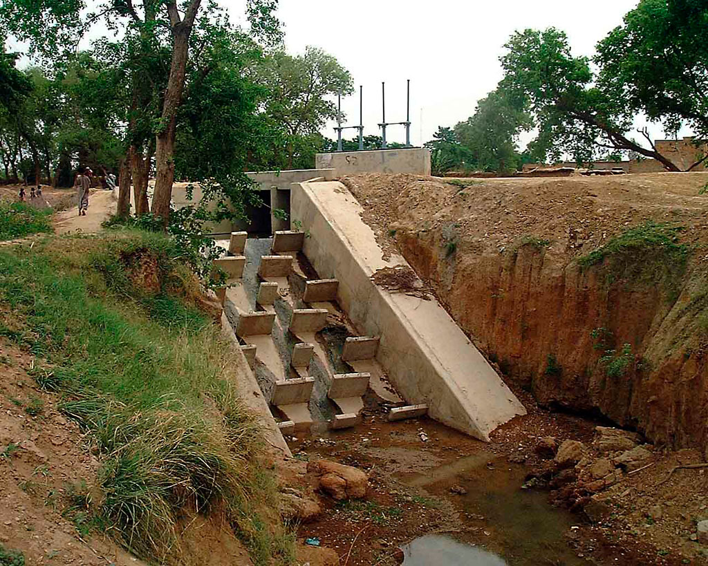
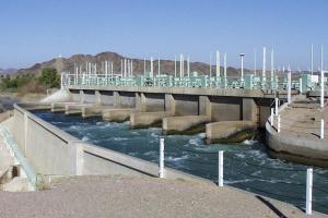
Typical Sloping Chute with baffle blocks (Pakistan)
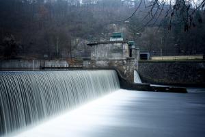
Sloping Chute
Recommendations
The following rules have been devised for the design of the sloping aprons developed from the foregoing discussion:
- Determine an apron arrangement which will give the greatest economy for the maximum discharge condition. This is a governing factor and the only justification for using a sloping apron.
- Position the apron so that the front of the jump will form at the upstream end of the slope for the maximum. Several trials will usually be required before the slope and location of the apron are compatible with the hydraulic requirement. It may be necessary to raise or lower the apron, or change the original slope entirely.
- The length of the jump for maximum or partial flows can be obtained from Hydraulic charts based on experiments. The stilling basin apron is a decision for the designer. The average overall apron averages 60 percent of the length of jump for the maximum discharge condition. The apron may be lengthened or shortened, depending upon the quality of the rock in the riverbed and other local conditions. If the apron is set on loose material and the downstream channel is in poor condition, it may be advisable to make the total length of apron the same as the length of jump.
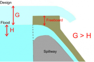
- With the apron designed properly for the maximum discharge condition, it should then be determined that the tail water depth and length of basin available for energy dissipation are sufficient. If the tail water depth is sufficient or in excess of the jump height for the intermediate discharges, the design is acceptable. If the tail water depth is deficient, it may then be necessary to try a different slope or reposition the sloping portion of the apron. It is not necessary that the front of the jump form at the upstream end of the sloping apron for partial flows.
- Horizontal and sloping aprons will perform equally well for high values of the Froude number if the proper tail water depth is provided.
- The slope of the chute upstream from a stilling basin has little effect on the hydraulic jump when the velocity distribution and depth of flow are reasonably uniform on entering the jump.
- A small solid triangular sill, placed at the end of the apron, is the only appurtenance needed in conjunction with the sloping apron. It serves to lift the flow as it leaves the apron and thus acts to control scour. Its dimensions are not critical; the most effective height is between O.O5D2 (D2= height after the jump) and O.10D2 and a slope of 3:1 to 2:1.
- The spillway should be designed to operate with as nearly symmetrical flow in the stilling basin as possible. (This applies to all stilling basins.) Asymmetry produces large horizontal eddies that can carry riverbed material on to the apron. This material, circulated by the eddies can abrade the apron and appurtenances in the basin at a very surprising rate. Eddies can also undermine wing walls and rip-rap. Asymmetrical operation is expensive operation, and operating personnel should be continually reminded of this fact.
- Where the discharge over high spillways exceeds 500 c.f.s. per foot of apron width, where there is any form of asymmetry involved and for the higher values of the Froude number where stilling basins become increasingly costly and the performance relatively less acceptable, a model study is advisable.