Methods of Pile Installation

Piles are relatively long and slender members used to transmit foundation loads through soil strata of low bearing capacity to deeper soil or rock having a higher bearing capacity. The method by which this occurs is the basis of the simplest pile type classification. We have two main Pile Types (Types of Piles):
1. End-Bearing piles

2. Friction (or floating) piles

For both pile types a further distinction is required based on their method of installation.
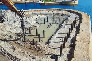
- Driven (or displacement) piles: These piles are generally pre-formed before being driven, jacked, screwed or hammeredinto the ground.
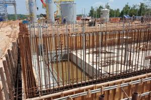
- Bored piles: For these piles a hole is first bored in the ground, andthe pile is then usually formed in thehole.
These categories may be further subdivided into:
Large Displacement
- Preformed – driven into the ground and left in position
- - Solid – Timber/Concrete
- - Hollow with a closed end – Steel or concrete tubes
- Formed in-situ – closed-ended tubular driven then withdrawn filling void with concrete
Small displacement
- Screw piles
- Steel tube and H-sections – (Tube sections may plug and become large displacement)
No displacement
- Void formed by boring or excavation then filled with concrete. During construction the hole may need to be supported for which there are two main options
- Steel Casing
- Drilling Mud
Loads applied to Piles
Combinations of vertical, horizontal and moment loading may be applied at the soil surface from the overlying structure. For the majority of foundations the loads applied to the piles are primarily vertical. Horizontal loads arising from wind loads on structures are usually relatively small and are ignored. However, for piles in jetties, foundations for bridge piers, tall chimneys, and offshore piled foundations the lateral resistance is an important consideration.
Only the analysis of piles subjected to vertical loads is considered here. The analysis of piles subjected to lateral and moment loading is more complex because of the nature of the soil-structure interaction. Apart from their ability to transmit foundation loads to underlying strata piles are also widely used as a means of controlling settlement and differential settlement. In these notes only the ultimate axial capacity is considered.
Vertically Loaded Piles
Ultimate Capacity of Single Piles
The total pile resistance may be split into components from the base and the shaft. Consideration of static equilibrium then gives the ultimate capacity as:

Pu = Psu + Pbu – W
Pu Ultimate load capacity of the pile
Pbu = Ultimate resistance at the base of the pile (Base resistance)
Psu = Ultimate side shear resistance on the pile shaft (Shaft resistance)
W = Self-weight of the pile
Base Resistance
In analysing pile behaviour it is conventional to express the ultimate base resistance by
Pbu = Ab ( fb + po)

Ab = Plan area of the pile base
fb = Net ultimate resistance per unit area of the base
po = Overburden pressure at the level of the base
If the pile does not extend above the soil surface it is found that the pile weight is usually similar to the force due to the overburden pressure. Thus
W ≈ Ab po
and Pu = Psu + Ab fb
Side Resistance

As = Surface area of pile shaft in contact with the soil
 = Average ultimate side resistance per unit area
In general, the side resistance will be a function of depth below the surface, because both the undrained strength su (short term undrained analysis) and the effective stresses (long term analysis) increase with depth. The average shear stress can be expressed mathematically as

where L is the length of the pile
Total stress analysis (clayey soils)
For these soils the limiting capacity is often controlled by the short term (undrained) condition.
Base resistance
This is a simple bearing capacity problem, that is

where qf is the ultimate bearing capacity. For a soil with fu = 0 the ultimate bearing capacity can be written
qf = Nc su + g D = Nc su + po
The net ultimate resistance is simply
fb = Nc su
and the ultimate base resistance approximately
Pbu = Ab (Nc su + po)
It is conventional to take cu = cub
where sub is the undrained shear strength of the soil at the pile base and to assume fu is zero. The value of Nc can then be obtained from Skempton’s chart (p28 Data Sheets) which is applicable for Φu = 0.
When using this chart it is important to check the length to diameter ratio L/D (D/B on the chart). It is normally assumed that pile bases may be treated as deep foundations and that Nc = 9. However, if L/D is less than 4, Nc will be lower than 9 as shown in the chart below and the ultimate capacity will be similarly reduced.

Side Resistance
Both total stress and effective stress methods of analysis are used to estimate the side resistance for saturated clays. Here we consider only the total stress or α method.

su (z) = undrained strength of the soil at depth z
α = an empirical reduction factor which depends on:
- Soil type
- Pile type
- Soil strength (see chart below, p105 Data Sheets)
- Method of installation
- Time since installation
In the absence of additional information the chart below may be used to estimate α.