Reinforced Cement Concrete Design - Concepts and Theories

Concrete:
Concrete is a stone like substance obtained by permitting a carefully proportioned mixture of cement, sand and gravel or other aggregate and water to harden in forms of the shape and of dimensions of the desired structure.
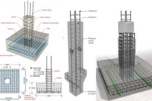
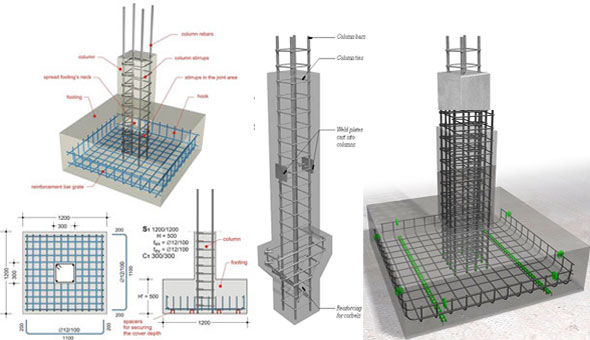
Reinforced cement concrete:
Since concrete is a brittle material and is strong in compression. It is weak in tension, so steel is used inside concrete for strengthening and reinforcing the tensile strength of concrete. The steel must have appropriate deformations to provide strong bonds and interlocking of both materials. When completely surrounded by the hardened concrete mass it forms an integral part of the two materials, known as "Reinforced Concrete".
Advantages and disadvantages of reinforced concrete
Flexural Strength of Concrete
Reinforced Concrete is a structural material, is widely used in many types of structures. It is competitive with steel if economically designed and executed.
Advantages of reinforced concrete
- It has relatively high compressive strength
- It has better resistance to fire than steel
- It has long service life with low maintenance cost
- In some types of structures, such as dams, piers and footings, it is most economical structural material
- It can be cast to take the shape required, making it widely used in pre-cast structural components
- It yields rigid members with minimum apparent deflection
- Yield strength of steel is about 15 times the compressive strength of structural concrete and well over 100 times its tensile strength
- By using steel, cross sectional dimensions of structural members can be reduced e.g in lower floor columns
Disadvantages of reinforced concrete
- It needs mixing, casting and curing, all of which affect the final strength of concrete
- The cost of the forms used to cast concrete is relatively high
- It has low compressive strength as compared to steel (the ratio is about 1:10 depending on material) which leads to large sections in columns/beams of multistory buildings Cracks develop in concrete due to shrinkage and the application of live loads
Factors affecting the joint performance of steel and Concrete
Reinforced cement concrete Design philosophy & concepts of RCC Design
The design of a structure may be regarded as the process of selecting proper materials and proportioned elements of the structure, according to the art, engineering science and technology. In order to fulfill its purpose, the structure must meet its conditions of safety, serviceability, economy and functionality.
| Serviceability: No excessive deflection, no excessive deformation and no cracking or vibrations No excessive reinforcement. Must be able to perform the function, it is built for. |
Strength design method
It is based on the ultimate strength of the structural members assuming a failure condition, whether due to the crushing of concrete or due to the yield of reinforced steel bars. Although there is additional strength in the bar after yielding (due to Strain Hardening), this additional strength in the bar is not considered in the analysis or design of the reinforced concrete members. In the strength design method, actual loads or working loads are multiplied by load factor to obtain the ultimate design loads. The load factor represents a high percentage of factor for safety required in the design. The ACI code emphasizes this method of design.
Working stress design
This design concept is based on elastic theory, assuming a straight line stress distribution along the depth of the concrete. The actual loads or working loads acting on the structure are estimated and members are proportioned on the basis of certain allowable stresses in concrete and steel. The allowable stresses are fractions of the crushing strength of concrete (fc') and the yield strength (fy). Because of the differences in realism and reliability over the past several decades, the strength design method has displaced the older stress design method.
Limit state design
It is a further step in the strength design method. It indicates the state of the member in which it ceases to meet the service requirements, such as, loosing its ability to withstand external loads or local damage. According to limit state design, reinforced concrete members have to be analyzed with regard to three limit states:
- Load carrying capacity (involves safety, stability and durability)
- Deformation (deflection, vibrations, and impact)
- The formation of cracks
The aim of this analysis is to ensure that no limiting sate will appear in the structural member during its service life.
Fundamental assumptions for Reinforced Concrete's Behavior
Reinforced concrete's sections are heterogeneous, because they are made up of two different materials - steel and concrete. Therefore, proportioning structural members by ultimate stress design is based on the following assumptions:
- Strain in concrete is the same as in reinforcing bars at the same level, provided that the bond between the concrete and steel is adequate
- Strain in concrete is linearly proportional to the distance from the neutral axis.
- Modulus of elasticity for all grades of steel is taken as Es = 29 x 106 psi. The stress in the elastic range is equal to the strain multiplied by Es.
- Plane cross sections continue to be plane after bending.
- Tensile strength of concrete is neglected because:
- Concrete's tensile strength is about 1/10 of its compressive strength.
- Cracked concrete is assumed to be not effective Before cracking, the entire cross section is effective in resisting the external moments.
- The method of elastic analysis, assuming an ideal behavior at all levels of stress is not valid. At high stresses, non-elastic behavior is assumed, which is in close agreement with the actual behavior of concrete and steel.
- At ultimate strength, the maximum strain at the extreme compression fibers is assumed to be equal to 0.003 by the ACI code provisions. At the ultimate strength, the shape of the compressive stress distribution may be assumed to be rectangular, parabolic or trapezoidal.
Loads
Structural members must be designed to support specific loads. Loads are those forces for which a structure should be proportioned. Loads that act on structure can be divided into three categories.
- Dead loads
- Live loads
- Environmental loads
Dead Loads:
Dead loads are those that are constant in magnitude and fixed in location throughout the lifetime of the structure. It includes the weight of the structure and any permanent material placed on the structure, such as roofing, tiles, walls etc. They can be determined with a high degree of accuracy from the dimensions of the elements and the unit weight of the material.
Live loads:
Live loads are those that may vary in magnitude and may also change in location. Live loads consists chiefly occupancy loads in buildings and traffic loads in bridges. Live loads at any given time are uncertain, both in magnitude and distribution.
Environmental loads:
Consists mainly of snow loads, wind pressure and suction, earthquake loads (i.e inertial forces) caused by earthquake motions. Soil pressure on subsurface portion of structures, loads from possible ponding of rainwater on flat surfaces and forces caused by temperature differences. Like live loads, environmental loads at any given time are uncertain both in magnitude and distribution.
ACI Code Safety Provisions
Structural members must always be proportioned to resist loads greater than service or actual loads, in order to provide proper safety against failure. In the strength design method, the member is designed to resist the factored loads which are obtained by multiplying the factored loads with live loads.
Different factors are used for different loadings. As dead loads can be estimated quite accurately, their load factors are smaller than those of live loads, which have a high degree of uncertainty. Several load factor conditions must be considered in the design to compute the maximum and minimum design forces. Reduction factors are used for some combinations of loads to reflect the low probability of their simultaneous occurrences. Now if the ultimate load is denoted by U, the according to the ACI code, the ultimate required strength U, shall be the most critical of the following
Basic Equation U = 1.2D + 1.6L
In addition to the load factors, the ACI code specifies another factor to allow an additional reserve in the capacity of the structural member. The nominal strength is generally calculated using accepted, analytical procedures based on statistics and equilibrium. However, in order to account for the degree of accuracy within which the nominal strength can be calculated and for adverse variations in materials and dimensions, a strength reduction factor (Ø) should be used in the strength design method. Values of the strength reduction factor Ø (Phi) are:
For flexure of tension controlled sections Ø = 0.9


	  For shear and torsion Ø = 0.75


	  For compression members with spiral reinforcement Ø = 0.70


	 For compression members with lateral ties Ø = 0.65
Nominal strength
Actual strength from the material properties is called the nominal strength.
Nominal x Ø = Design strength
As safe design is achieved when the structural strength obtained by multiplying the nominal strength by the reduction factor Ø, exceeds or equals the strength needed to withstand the factored loads.